


Quality Products
This is a sample of our offerings, Please contact us for additional information and inquiries


Heat Shrinkage Tubes
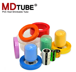
PVC Heat Shrinkable Tube
Application: Capacitors, battery package, electronic/electrical insulations, sealer, various packaging use.

PET Heat Shrinkable Tube
Eco-Friendly product that satisfies European standards.
Application: Refrigerator elements - Condenser, Compressor, Hot tube, Suction, Dryer, Capillary and etc.)
Capacitor: Radial, Axial, Snap-In, Screw Bolt

Metalized Polypropylene & Polyester Film


Wires

Copper Clad Steel Wire
Special conductors of cable wires having electric and physical properties defined by international standard such as ASTM, BS.
Application
Electrical conductors for Drop cable, Data transmission cable, Micro-coaxial cable, especially for ground earthing conductors with stranded replacing by pure copper.
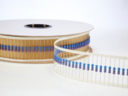
Lead Wires
Lead wire for interconnecting main electronic components with PCB board in order to activate each component with electrical & physical properties
Application
Capacitors (Electrolytic, Polymer Solid, Film, Ceramic), Resistor, Diode, Varistor, Jumper, Connector Pin.


Aluminum Wires
High purity Aluminum wire with 99.92% level
Application
Electrolytic capacitor, Polymer solid capacitor, Rivet for high voltage capacitor, Film deposition, Accessories, flowering.
Hot-Dipped Lead Wires
Hot-dopped type lead wire having proved whisker-free solution and heat resistant properties with tight tolerance of tin coating thickness on the wire.
Application
Electrolytic capacitor, Polymer solid capacitor, Rivet for high voltage capacitor, Film deposition, Accessories, flowering.

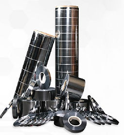
Adhesive Tape & Reel

Industrial Strength
High Temperature Resistance
Highly adhesive tape
Fuel Cell Generator (Energy of Future)
_edited.png)

Environmental friendly energy solution
Proven technology
Long history of service
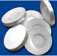
Aluminum Slugs


99.7 % Pure aluminum
ISO 9001
Halogen Free Product
Terminals for Capacitors


High quality capacitor terminals for many applications
ISO 9001
Digital Pens
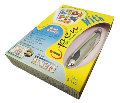

* Wacky Art Tools & Crazy Effects
* Picture Starters & School Projects
* Emal your Art
* Stickers and Animations
* Music & Sound Effects
* Paint with your voice
* Type and Hear It!
